

Fluid Meter
一、Overview
Our intelligent differential pressure flowmeter includes orifice flowmeter and wedge flowmeter, which can be used for gas measurement and liquid measurement. Those are designed, installed and used in accordance with 1S05167 international standard and (or) GB/T2624 national standard, which are called standard throttling devices, and others are called non-standard throttling devices. The amount of standard throttling device is more than that of the latter, while the structure, variety, caliber and applicable medium conditions of non-standard throttling device are far more than that of the former.
二、Orifice flowmeter
1、Operating Principle
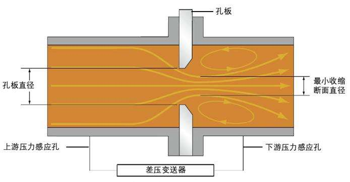
When the fluid filled in the pipeline flows through the throttling device in the pipeline, the flow will form local contraction at the throttling part to increase the flow rate, and the static pressure will be reduced to, so the static pressure difference will be generated before and after the throttling part. The greater the flow rate of the fluid, the greater the differential pressure value before and after the throttling part, so the flow rate of the fluid flowing through the throttling device can be measured by measuring the differential pressure. This measurement is based on the law of conservation of energy and the continuity equation of the flow.
The relationship between flow rate and differential pressure is determined by the following formula:
qm=C/(1-β4)0.5×ξ×π/4×d2( 2△Pρ1)0.5
qv= qm/ρ1
qm:Mass flow rate kg/s
qv:Volumetric flow rate m3/s
C:Flow coefficient dimensionless
ξ:Expansion factor dimensionless
d :Diameter of the orifice in the throttling device m
△P:Differential pressure Pa
ρ1:Fluid density kg/ m3

Schematic diagram of orifice plate measurement principle

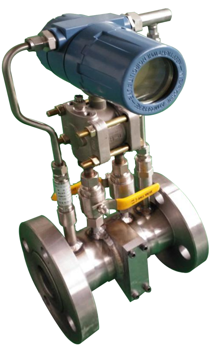
Orifice flowmeter
2、Applicable Range
It can be widely used in petroleum, chemical industry, natural gas, metallurgy, electric power, pharmaceutical and other industries to continuously measure the volume flow or mass flow of various liquids, gases, natural gas and steam.
3、Technical parameters, specifications and models
|
型号 |
BK-50/63-F |
BK-80/63-F |
BK-100/63-F |
BK-150/63-F |
|
承载压力 |
2.5MPa、4.0MPa、6.3MPa、10MPa、16MPa、25MPa |
|||
|
安装方式 |
法兰连接 |
|||
|
接线标志 |
两线制 |
两线制 |
两线制 |
两线制 |
|
工作温度 |
-30~70℃ |
-30~70℃ |
-30~70℃ |
-30~70℃ |
|
信号输出 |
4~20mA |
4~20mA |
4~20mA |
4~20mA |
|
电源 |
10.5~55V DC |
10.5~55V DC |
10.5~55V DC |
10.5~55V DC |
|
测量精度 |
1.0级 |
1.0级 |
1.0级 |
1.0级 |
|
Model |
BK-50/63-F |
BK-80/63-F |
BK-100/63-F |
BK-150/63-F |
|
Bearing pressure |
2.5MPa、4.0MPa、6.3MPa、10MPa、16MPa、25MPa |
|||
|
Installation method |
Flange connection |
|||
|
Wiring marks |
Two-wire system |
Two-wire system |
Two-wire system |
Two-wire system |
|
Operating temperature |
-30~70℃ |
-30~70℃ |
-30~70℃ |
-30~70℃ |
|
Signal output |
4~20mA |
4~20mA |
4~20mA |
4~20mA |
|
Power source |
10.5~55V DC |
10.5~55V DC |
10.5~55V DC |
10.5~55V DC |
|
Measurement accuracy |
1.0Level |
1.0Level |
1.0Level |
1.0Level |
4、Product features
The product is easy to disassemble and maintain. The orifice plate flowmeter can still work normally in the field extreme environment, with the stable performance and high measurement accuracy,and with no moving parts and not easy to be worn. The orifice flowmeter has the advantages of simple structure, convenient installation and maintenance-free. The orifice plate flowmeter can be used in the desert at -40 ℃ ~ 80 ℃, and the design avoids the problem of freezing and blocking of the impulse pipe caused by low temperature.
5、Integration of orifice plate flowmeter
This orifice plate flow meter integrates the flow computer into the head, making installation easier and maintenance more convenient. It can locally display instantaneous flow rate, cumulative flow, temperature, and pressure. At the same time, it transmits data to the monitoring system via RS-485.

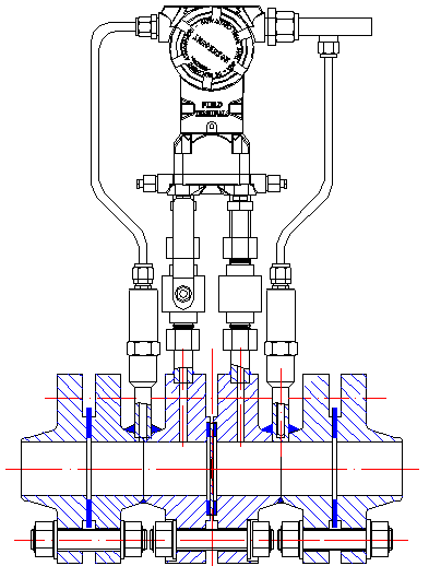
Schematic Diagram of Intelligent Orifice Flowmeter
6、Product configuration
The orifice plate flow meter is generally installed downstream of the emergency shutoff device on the wellhead gas extraction tree to measure the flow data of a single well in real time. Its main configuration includes: differential pressure transmitter, pressure transmitter, temperature transmitter, LCD display head, pressure guiding tube, ball valve, pressure tapping flange, throttling device, and connecting flange.
1)Nominal diameter: DN50 、DN65 、DN80 、DN100 、DN125、DN150。
2)aperture ratio β:0.1≤β<0.75
3)Reynolds number range:5000≤ReD And170β2 D≤ReD
When0.56< β,16000β2 D≤ReD
4)Nominal pressure:2.5MPa、4.0MPa、6.3MPa、10.0MPa、16.0MPa、25.0MPa
5)Accuracy:1.0Level
6)Working temperature: -40 ℃ ~ 80 ℃
7) Operating voltage: 9 ~ 36 DCV
8) Protection grade: IP65
9) Explosion-proof sign:Exia IICT4
10) Output signal: RS-485
11) Communication protocol: standard Modbus RTU
12) Electrical connection: M20 * 1.5 connecting thread
13) Transmission data: standard instantaneous flow (m3/H), cumulative flow (m3), temperature (℃), pressure (MPa)
三、Wedge flowmeter
1、 Overview
The wedge flowmeter is used to measure the dirt entrained in gas or liquid. The dirt can be taken away from the bottom of the wedge. It is generally installed downstream of the natural gas well to measure the flow data of a single well in real time.
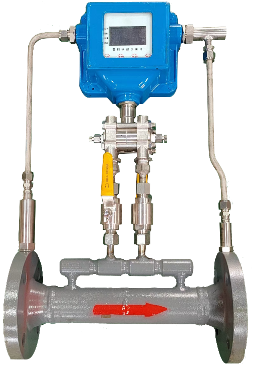
It is mainly equipped with multi-parameter flow calculator, differential pressure transmitter, pressure transmitter, temperature transmitter, liquid crystal display meter, ball valve, throttling parts and connecting flange. The wedge flowmeter is shown in the following figure:

图Outline Diagram of Intelligent Wedge Flowmeter
1) Flow calculator: It is used to collect differential pressure, pressure and temperature signals, process the original signals and display the data locally, and upload the data through RS-485.
2) Differential pressure transmitter: it is used to collect the differential pressure signal generated by the upstream and downstream of the orifice plate.
3) Pressure transmitter and temperature transmitter: it is respectively used for pressure measurement and medium temperature measurement of the pipeline.
4)Ball valve: the ball valve can be closed when maintaining and testing the flow calculator.
5) Connecting flange: it is used to install the orifice flowmeter and connect the gas pipeline.
2、Scope of application
It can be widely used in petroleum, chemical industry, natural gas, metallurgy, electric power, pharmaceutical and other industries to continuously measure the volume flow or mass flow of various liquids, gases, natural gas and steam.
3、Operating Principle
When the fluid filled in the pipeline flows through the throttling device in the pipeline, the flow will form local contraction at the throttling part to increase the flow rate, and the static pressure will be reduced to, so the static pressure difference will be generated before and after the throttling part. The greater the flow rate of the fluid, the greater the differential pressure value before and after the throttling part, so the flow rate of the fluid flowing through the throttling device can be measured by measuring the differential pressure. This measurement is based on the law of conservation of energy and the continuity equation of the flow.
4、Main functions and features
(1) The wedge-shaped flowmeter can still work normally in the extreme environment of the field, with stable performance, high measurement accuracy, no moving parts, and not easy to be worn. It is with a simple structure, convenient installation and simple maintenance. The wedge-shaped flowmeter can be used in the extreme field environment of -40 ℃ ~ 80 ℃, and the design avoids the problem of freezing and blocking of the impulse pipe caused by low temperature.
(2) when the measured medium is mixed with mud, sand and gravel, the measurement can still be carried out, and the accumulation of impurities in the flowmeter is avoided.
(3) When the Reynolds number is low, the wedge flow can still be measured normally, and the turndown ratio is high.
5、Technical parameters
1) Nominal diameter:DN50、DN65、DN80、DN100、DN150、DN200、DN250、DN300。
2) Wedge ratio:0.2<h/D<0.6
3) Reynolds number range:1000≤ReD
4) Nominal pressure:16MPa、4.0MPa、6.3MPa、10.0MPa、16.0MPa、25.0MPa
5) Accuracy:1.0Level
6) Working temperature: -40 ℃ ~ 80 ℃
7) Operating voltage: 9 ~ 36 DCV
8) Protection grade: IP65
9) Explosion-proof sign:Exia IICT4
10) Output signal: RS-485
11) Communication protocol: standard modbus RTU
12) Electrical connection: M20 * 1.5 connecting thread
13) Transmission data: standard instantaneous flow (m3/H), cumulative flow (m3), temperature (℃), pressure (MPa) and differential pressure (KPa).
Address of the unit: Building 12, No. 8, Heying Road, Nanshao Town, Changping District, Beijing
Tel: 010-64856065
Unit address: 18th Floor, Tianxin Building, No. 27, Fengcheng 2nd Road, Weiyang District, Xi'an
Tel: 029-86101780

©2025 Polydoctor Petroleum Technology Co., Ltd.,Beijing Ministry of Public Security Registration Number:11011402012372 Ministry of Industry and Information Technology Registration Number:Beijing ICP No. 05044633-1