

Integrated intelligent terminal
1.1 PDPT-801
1.1.1 PDPT-801 Generally State
PDPT-801 programmable logic controller is a product of 800 series PLC of our company, with operating frequency of 72 MHz, ARM industrial CPU, embedded operating system, 512K user program storage area and 100K user data storage area. The programming software uses STEP 7 MicroWIN, which can download the program through Ethernet and serial port. In addition, there are 2 RS485 interfaces. PDPT-801 integrated 24-channel DI and 16-channel DO single module can be flexibly applied to various small industrial automatic control occasions.

● Physical properties
|
size |
125x100x80mm |
|
weight |
0.2kg |
|
Installation |
Standard rail mounting |
|
Operating temperature |
-40ºC reach 85 ºC |
● Power supply characteristics
|
Enter the power supply
|
Rated voltage |
24VDC |
|
Allowable Scope |
18VDC to 28VDC |
|
|
Current rating |
200mA/24VDC(DO,AO,24VOUT When fully loaded) 100mA/24VDC(DI, the network port is fully loaded, 24VOUT empty Load time) 80mA/24VDC(DO,DI,24VOUT When all are unloaded) |
|
|
|
POWER(L N ) |
● Communication systems
|
Ethernet |
1 way |
RJ45 interface 10M/100M, program download port. Fixed IP192.168.1.206 |
|
RS485 |
3 ways |
DB9 interface (7 pin B, 3 pin A) is RS485 1 port; (terminals A, B) is RS485 0 port; MODBUS/RTU Master Slave defaults: 9600,1,8,E, address 1. |
|
Stop switch |
2 Location |
run/Stop (stop state only.) PLC The program does not run) |
|
Light |
45 piece |
RUN Running lights(solid green), STOP (stop, solid red), EROOR (fault, solid yellow); DIa (digital I0.0-I0.7 input indicator) ;D Ib (digital I1.0-I1.7 input indicator); DIc (Digital I2.0-I2.7 Input Indicator), LINK Ethernet Connection Indicator, DATA Ethernet Communication Indicator |
● Memory characteristics
|
User program memory |
512 k BYTE |
|
User data storage |
100 K BYTE |
|
Back-up battery data storage |
1K BYTE |
|
Data back-up time |
1 year |
●Memory characteristics
|
CPU frequency |
CPU frequency |
CPU frequency |
|
48MHz |
48MHz |
48MHz |
|
*big 72MHz |
*big 72MHz |
*big 72MHz |
|
* Small instruction scanning time |
* Small instruction scanning time |
* Small instruction scanning time |
|
10ms |
10ms |
10ms |
|
Integer, bit commands |
Integer, bit commands |
Integer, bit commands |
I/O characteristics
|
ype |
Points |
illustrate |
|
Digital inputs |
8 |
Optocoupler isolated inputs |
|
Digital output |
8 |
Relay output |
|
Analog inputs |
16 |
4—20mA input |
|
I/O status indicator |
16 |
|
I/O Parameters
1. Digital input parameters
The digital input is passive and it can use 24VDC with an isolated output inside the PLC
|
Input method |
Optical Lotus Isolation (Dual-Guiding Transparent Lotus Root) |
|
|
|
Functional configuration |
The first group |
The second group |
The second group |
|
Enter the number of points |
8 |
8 |
8 |
|
Input terminals |
DI0(I0.0~I0.7,M) |
DI1(I1.0~I1.7 and M) |
DI1(I2.0~I2.7 and ) |
|
Rated voltage |
24VDC |
24VDC |
24VDC |
|
ON voltage |
16VDC arrive 36VDC, |
16VDC arrive 36VDC |
16VDC arrive 36VDC |
|
OFF voltage |
-6VDC arrive 6VDC |
-3VDC arrive 3VDC |
-3VDC arrive 3VDC |
|
Input resistance |
20K |
20K |
20K |
|
Operating current |
about 1.1mA(24VDC) |
about 1.1mA(24VDC) |
about 1.1mA(24VDC) |
|
Enter the instructions |
Compatible terminals LED Indicator, the indicator light is on when there is input |
|
|
2. Digital output parameters
The digital output is the normally open contact output of the relay, with the contact of the relay directly connected to the output terminal.
|
Output mode |
Relays |
|
Number of output points |
16 |
|
Output terminals |
DO(Q0.0~Q0.7,1L;Q1.0~Q1.7,2L) |
|
Resistive loads |
5A/220VAC |
|
Output indications |
The LED indicator of the corresponding terminal is illuminated, and the relay timing light is on |
|
Response time |
≤20ms |
|
Mechanical life |
rated 200 10,000 times |
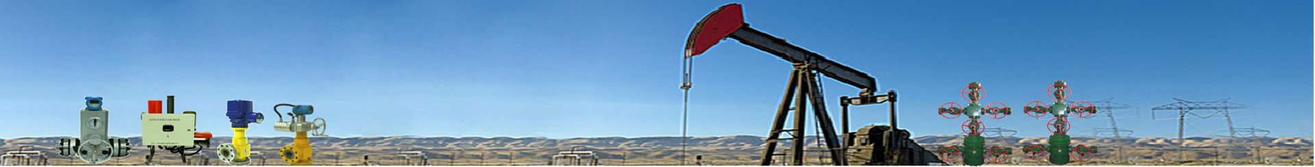
1.2 AE11
1.2.1 AE11 general statement
AE11 controller is our company's PDPT-800 series PLC supporting analog expansion module, using frequency 72MHz, ARM industrial grade CPU, embedded operating system, 1 RS232/485 interface. AE integrates 11 analog input interfaces.
1.2.2Physical Characteristics
|
size |
45x100x80mm |
|
weight |
0.1kg |
|
Installation |
Standard rail mounting |
|
Operating temperature |
-40ºC reach 85 ºC |
● Technical parameters
|
Supply voltage |
10~30V DC |
|
Supply current |
0.1A |
|
Methods of Communication |
RS485 (Isolated/Non-Isolated) |
|
Input current |
4~20mA |
|
Number of input channels |
1~11 routes |
|
resolution |
12 bits, voltage: 1mV, current: 1μA |
|
precision |
±1% (1 percent) |
|
Communication protocols |
Modbus RTU, address 0XA5; Baud rate 9600,8,1,N |
|
Support directives |
Read hold registers 03H, write a single hold register 06H, input register definition 04H |
|
Correspondence address |
1~255 can be set and saved when power is off |
|
baud rate |
The 9600 can be set and saved when the power is off |
|
Light |
Power/Communications |
|
Protection features |
Over-current/over-voltage/reverse connection/lightning surge protection |
|
Operating temperature |
-40℃~+85℃ |
|
Operating humidity |
0%~85%RH (no condensation) |
● Register type
This series uses the hold register in the Modbus RTU to set the input current value, and the register contents are saved after power-off. The hold registers act as readable and writable registers, and the values in each register are 16-bit unsigned integers with a fixed decimal point to represent the actual input current value.
● Hold register function definitions
This series uses the hold registers in the Modbus RTU to set the input current value. The hold registers are readable and writable registers, and the values in each register are 16-bit unsigned integers with a fixed decimal point to represent the actual input current value.
The function definition of the hold register is shown in Table 2.1.
|
Hold Register Function Definition (Function Code 03) |
|||
|
address |
definition |
range |
illustrate |
|
40118 |
Device address |
1-255 |
Magnum address 165 |
|
40119 |
Analog channel 1 correction |
0-200 |
The correction range is -0.0625-+0.0625mA, and 100 means that the correction value is 0. |
|
40120 |
Analog channel 2 correction |
0-200 |
The correction range is -0.0625-+0.0625mA, and 100 means that the correction value is 0. |
|
40121 |
Analog channel 3 correction |
0-200 |
The correction range is -0.0625-+0.0625mA, and 100 means that the correction value is 0. |
|
40122 |
Analog channel 4 correction |
0-200 |
The correction range is -0.0625-+0.0625mA, and 100 means that the correction value is 0. |
|
40123 |
Analog channel 5 correction |
0-200 |
The correction range is -0.0625-+0.0625mA, and 100 means that the correction value is 0. |
|
40124 |
Analog channel 6 correction |
0-200 |
The correction range is -0.0625-+0.0625mA, and 100 means that the correction value is 0. |
|
40125 |
Analog channel 7 corrections |
0-200 |
The correction range is -0.0625-+0.0625mA, and 100 means that the correction value is 0. |
|
40126 |
Analog channel 8 correction |
0-200 |
The correction range is -0.0625-+0.0625mA, and 100 means that the correction value is 0. |
|
40127 |
Analog channel 9 correction |
0-200 |
The correction range is -0.0625-+0.0625mA, and 100 means that the correction value is 0. |
|
40128 |
Analog channel 10 correction |
0-200 |
The correction range is -0.0625-+0.0625mA, and 100 means that the correction value is 0. |
|
40129 |
Analog channel 11 correction |
0-200 |
The correction range is -0.0625-+0.0625mA, and 100 means that the correction value is 0. |
● the definition of the input register
The input register functions are defined as shown in the table 2.2.
|
Modbus address |
Device address |
content |
illustrate |
|
30001-30011 |
165 |
Native 11 analogue inputs |
Units of current mA, Data parsing method: Divide the value in the hold register by 1600 to get the current channel current input value. |
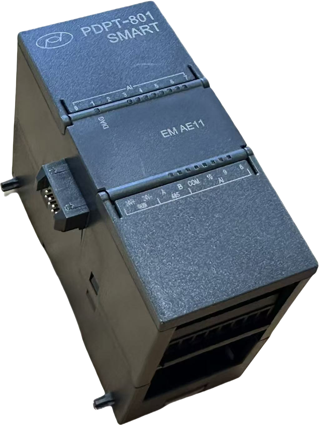
1.3 AQ06
1.3.1 AQ06 general statement
AQ061 controller is the analog output expansion module supporting our company's PDPT-800 series PLC with the frequency of use72MHz, ARM Industrial grade CPU,, embedded operating system,1 road RS232/485 Interface.AQ06 integration 6 road Analog output interface。
1.3.2 Physical Properties
|
size |
45x100x80mm |
|
weight |
0.1kg |
|
Installation |
Standard rail mounting |
|
Operating temperature |
-40ºC reach 85 ºC |
● Technical parameters
|
Supply voltage |
10~30V DC |
|
Supply current |
0.1A |
|
Methods of Communication |
RS485 (Isolated/Non-Isolated) |
|
Output current |
4~20mA |
|
Number of input channels |
Route 1~6 |
|
resolution |
16 bits, voltage: 1mV, current: 1μA |
|
precision |
±1% (1 percent) |
|
Communication protocols |
Modbus RTU, address 0XA5; Baud rate 9600,8,1,N |
|
Support directives |
Read hold registers 03H, write a single hold register 06H, input register definition 04H |
|
Correspondence address |
1~255 can be set and saved when power is off |
|
baud rate |
The 9600 can be set and saved when the power is off |
|
Light |
Power/Communications |
|
Protection features |
Over-current/over-voltage/reverse connection/lightning surge protection |
|
Operating temperature |
-40℃~+85℃ |
|
Operating humidity |
0%~85%RH (no condensation) |
● Register type
This series is used The hold register in the Modbus RTU sets the input current value, and the register content is saved when the power is off. The hold registers are readable and writable registers, and the values in each register are 16-bit unsigned integers with a fixed decimal point to represent the actual input current value.
● Enter the register function definition
This series is used The hold registers in the Modbus RTU set the input current value. The hold registers are readable and writable registers, and the values in each register are 16-bit unsigned integers with a fixed decimal point to represent the actual input current value.
|
Modbus address |
PLC address |
content |
illustrate |
|
0BH |
40012 |
The address of the machine |
The address can be customized, and its range is 1~255, of which OXFE is the universal address |
|
0CH |
40013 |
clause1channel analog output |
clause1analog output, Units of current mA, Data parsing method: Convert the value in the hold register to a floating-point number and divide by1000Get the current output value of the current channel. |
|
0DH |
40014 |
clause2channel analog output |
clause2The analogue output is described in the same section1road |
|
0EH |
40015 |
clause3channel analog output |
clause3The analogue output is described in the same section1road |
|
0FH |
40016 |
clause4channel analog output |
clause4The analogue output is described in the same section1road |
|
10H |
40017 |
clause5channel analog output |
clause5The analogue output is described in the same section1road |
|
11H |
40018 |
clause6channel analog output |
clause6The analogue output is described in the same section1road |
|
12H |
40019 |
clause7channel analog output |
clause7The analogue output is described in the same section1road |
|
13H |
40020 |
clause8channel analog output |
clause8The analogue output is described in the same section1road |
1.4 DR32
1.4.1 DR32 General Statement
DR32 controller is our company's PDPT-800 series PLC supporting digital input and output expansion module, using frequency 72MHz, ARMIndustrial gradeCPU,Embedded operating systems, 1road RS232/485Interface. AQ06integration6Analog output interface。

1.4.2 Physical Characteristics
|
size |
70x100x80mm |
|
weight |
0.15kg |
|
Installation |
Standard rail mounting |
|
Operating temperature |
-40ºC reach 85 ºC |
I/O Parameters
1. Digital input parameters
The digital input is passive and can use 24VDC with an isolated output inside the PLC.
|
Input method |
Optical Lotus Isolation (Dual-Guiding Transparent Lotus Root) |
|
|
Functional configuration |
The first group |
The second group |
|
Enter the number of points |
8 |
8 |
|
Input terminals |
DI0(I0.0~I0.7,M) |
DI1(I1.0~I1.7 and M) |
|
Rated voltage |
24VDC |
24VDC |
|
ON voltage |
16VDC arrive 36VDC, |
16VDC arrive 36VDC |
|
OFF voltage |
-6VDC arrive 6VDC |
-3VDC arrive 3VDC |
|
Input resistance |
20K |
20K |
|
Operating current |
about 1.1mA(24VDC) |
about 1.1mA(24VDC) |
|
Enter the instructions |
Compatible terminals LED Indicator, the indicator light is on when there is input |
|
2. Digital output parameters
The digital output is the normally open contact output of the relay, and the contact of the relay is directly connected to the output terminal.
|
Output mode |
Relays |
|
Number of output points |
16 |
|
Output terminals |
DO(Q0.0~Q0.7,1L;Q1.0~Q1.7,2L) |
|
Resistive loads |
5A/220VAC |
|
Output indications |
The LED indicator of the corresponding terminal is illuminated, and the relay timing light is on |
|
Response time |
≤20ms |
|
Mechanical life |
rated 200 10,000 times |
● Register type
This series uses the hold register in the Modbus RTU to set the input current value, and the register contents are saved after power-off. The hold registers act as readable and writable registers, and the values in each register are 16-bit unsigned integers with a fixed decimal point to represent the actual input current value.
This series uses the hold registers in the Modbus RTU to set the input current value. The hold registers are readable and writable registers, and the values in each register are 16-bit unsigned integers with a fixed decimal point to represent the actual input current value.
The function definition of the hold register is shown in Table 2.1.
|
Modbus address |
PLC address |
content |
illustrate |
|
0BH |
40012 |
The address of the machine |
The address can be customized, and its range is 1~255, of which OXFE is the universal address |
|
0CH |
40013 |
clause1channel analog output |
clause1analog output, Units of current mA, Data parsing method: Convert the value in the hold register to a floating-point number and divide by1000Get the current output value of the current channel. |
|
0DH |
40014 |
clause2channel analog output |
clause2The analogue output is described in the same section1road |
|
0EH |
40015 |
clause3channel analog output |
clause3The analogue output is described in the same section1road |
|
0FH |
40016 |
clause4channel analog output |
clause4The analogue output is described in the same section1road |
|
10H |
40017 |
clause5channel analog output |
clause5The analogue output is described in the same section1road |
|
11H |
40018 |
clause6channel analog output |
clause6The analogue output is described in the same section1road |
|
12H |
40019 |
clause7channel analog output |
clause7The analogue output is described in the same section1road |
|
13H |
40020 |
clause8channel analog output |
clause8The analogue output is described in the same section1road |
★Application examples
In recent years, with the implementation of the national energy conservation and emission reduction policy, the consumption of natural gas has been increasing year by year, and the number of gas wells produced and built in gas fields has also increased. At the same time, with the rapid development of science and technology, the digital construction of production and construction wells in oil and gas fields has put forward the requirements of simple and fast construction, convenient operation and maintenance. In response to the above problems, our company has developed an all-in-one controller with complete functions, high integration, stable and reliable performance to meet the needs of the current market changes. It mainly includes embedded PLC modules, integrated control microcontroller modules, 4G/5G mobile networks, ARM switches, 485 isolators, surge lightning protection, etc. More than 100 sets have been applied in the field at present with the stable operation.


On-site application of physical photos
Address of the unit: Building 12, No. 8, Heying Road, Nanshao Town, Changping District, Beijing
Tel: 010-64856065
Unit address: 18th Floor, Tianxin Building, No. 27, Fengcheng 2nd Road, Weiyang District, Xi'an
Tel: 029-86101780

©2025 Polydoctor Petroleum Technology Co., Ltd.,Beijing Ministry of Public Security Registration Number:11011402012372 Ministry of Industry and Information Technology Registration Number:Beijing ICP No. 05044633-1